 There are two styles of coils that will fit the 1929 and 1930 Plymouths, one with two wire terminals , not including the distributor wire, and another with three with terminals. The question is , which is correct for what model year Plymouth? The front ignition switch and bezel plate look to be the same. With making part changes through the model year were both versions used in any model year? Just wondering Thanks in advance. - Rich
- Welcome to 28Q29U Plymouth Forum.
28Q29U Plymouth Forum
News:
NEW FORUM version is here.
If you are experiencing any problems, contact chetbrz@aol.com
WELCOME Auto Registration is turned OFF.
In order to register for this forum please contact chetbrz@aol.com to request access.
This section allows you to view all posts made by this member. Note that you can only see posts made in areas you currently have access to.
#21
General Discussion / Ignition switch/coil ID on '29 and '30 Plymouths?
March 28, 2011, 04:35:01 PM There are two styles of coils that will fit the 1929 and 1930 Plymouths, one with two wire terminals , not including the distributor wire, and another with three with terminals. The question is , which is correct for what model year Plymouth? The front ignition switch and bezel plate look to be the same. With making part changes through the model year were both versions used in any model year? Just wondering Thanks in advance. - Rich
#22
General Discussion / Top Material Pattern??
February 02, 2011, 12:31:12 AM
Have been wondering what the original top material pattern was on a 1929 Ply. Is there a photo of it anywhere? Black in color I assume but was it long grained, dotted, textured or ? Thanks - Rich
#23
General Discussion / 1929 PlymouthHead light lens info
November 26, 2010, 01:19:02 AMHeadlight Lens Info for 1929 Plymouth "U"
Up to 1560970 US built use part #300153 (DEPRESSED LENS)
After 156970 US built use part #321768 (TWILIGHT LENS)
#24
General Discussion / Head light switch wiring schematic (not in Mopar manuals)
November 21, 2010, 02:05:21 AM
While making a new wiring harness, kept track of some wiring information not found in any Plymouth manuals. There are numbers embossed on the head-light switch and on the face of the head-light connector plugs. They are referenced to in this chart. The head-light plugs can only be inserted in the right orientation as the two twist lock pins are not straight apart.
One interesting thing is the 1929 Plymouth "U" has a #1000 head-light bulb that has a designation of , 32-32 CP (candle power) That means the low beam and high beam is the same power and only one filament lights at a time. ?? The Plymouth "Instruction Manual" explains how to adjust the beam with the screw in the back of the head-light buckets, so my guess is the refraction in the "Depressed Beam" lens must make the difference in the low and high beams. Any ideas on this mystery?
In reference to the wiring schematic in the "Plymouth Instruction Manual";
#42 parking light wire is BROWN (#3 on switch)
#43 high beam wire is RED (#4 on switch)
#44 low beam wire is BLACK (#6 on switch)
To save & copy wiring chart click on the attachment title.
#25
General Discussion / The End Of 70 deg Days!!!!
November 13, 2010, 06:17:16 PM ***** HAPPY HOLIDAYS *****
It was nice while 70 deg. days lasted and the honey do list got a little shorter. The engine, transmission, new drive discs and drive shaft are in and ready to go, so the indoor projects can start up again. The vintage wiring for the new wiring harness came in so will concentrate on getting that made the next few days as it is 50 deg. outside. Wheels will go to soda blaster, then soak in linseed oil for preservation and to tighten the fellows and be refinished to natural wood and pinstriped. I'm counting on a few more warm spells to get the body ready for paint next spring. So much to do, so little time! Any information you might add on my projects planned here can help me and other members, Please add your DO'S & DONT'S or comments. Happy Motoring!!!! - Rich #26
General Discussion / Head light connector wiring
October 28, 2010, 06:19:07 PM In an effort to get a new wiring harness made I find a lot of details missing in the 1929 Plymouth Instruction Booklet. As noted in a prior thread the steering wheel switch terminals have numbers stamped above them and ARE NOT IN NUMERICAL ORDER. From the terminal next to the engine they are numbered ; 1,3,2,4,6,5. The wiring diagram in the book shows three wires to both head lights, one red, one black and one brown. The terminals on the switch that are used for the hdlights are #3, #4, #6. The question is witch color red, black and brown wire goes to witch terminal.
On the other end of these three wires that go to the round head light connector, the round connector is numbered on the face of the connector #1,#2,#3. From the keyed slot in the connector (facing straight up at 12 o'clock) #1 is to the right, #2 is to the left and #3 centered at the bottom.
The question is which number on the terminal is red, black and brown.
The diagram in the manual shows #42 as brown, #43 as red and #44 as black but the fine details as to the correct numbers are left out. I am going to try to incorporate all the wiring info learned on this project onto an updated wiring diagram and post it on the forum. Thanks for any help. Happy Holidays! & Happy Motoring!!!! - Rich

#27
General Discussion / My Rearend Improvments !!!!!!!!!!!!!
October 05, 2010, 01:53:46 PM
With the weather improving, down to less then 90 + degrees, managed to get a
few items taken care of on my 29 Ply. Droped the rear-end and did a
complete cleanup and paint. If you need a GREAT cleaner for such
projects PURPLE POWER is great and available at your auto parts
or hardware. Then made new copper brake lines, wire brushed all the
brass fittings and reinstalled. As the brake lines run along the front
of the housing, at some time something must have flew up and hit one of
the old ones had been flatted it. One side had a RUSTY steel spring
around the length of it for protection but the side that was flattened
did not. I am not sure if the spring was a factory item or not but I
like it and decided to replace the new brake lines with new springs
installed. The springs I used were screen door springs bought at the
hardware store and fit perfect. Had to try three stores to find a brand
of springs that fit the lines. Some springs are smaller and larger
inside diameter. Finally came up with STANLEY brand that were
just right. If you decide to replace you lines with springs installed
don't forget to leave the spring a little short on one end to get the
flaring tool on the tubing. See before and after photos below HAPPY MOTORING !!!! -
Rich
#28
General Discussion / Engine Dust Pan Parts '29 Ply
August 10, 2010, 08:55:36 AM (1929 Plymouth 4 cyl.) The engine dust pan on the right side has a cutout for the the exhaust pipe to pass through. To the front and back of the cutout are two holes to attach something. These were missing when I purchased my Coupe. Does anyone have a photo of these parts or a description so I can make replacement? Thanks - Rich
#29
General Discussion / Removal of Horn Button Wire '29 Ply
August 07, 2010, 03:01:23 AM
Has anyone removed the horn button and cover from the steering wheel? I would like to replace the old wire that goes down through the steering column and can not find out how to remove the horn button from the steering wheel. Thanks - Rich
#30
General Discussion / Speedometer 1931 Plymouth photo needed
December 29, 2009, 01:17:06 AM
Does anyone have a photo of the face of a 1931 Plymouth speedometer? Please post. Thank you. - Rich
#31
General Discussion / To see photos in threads
October 30, 2009, 09:10:01 PM Just a reminder to new & old members of the forum. To see any photos that are attached to any threads you must register to this forum and log in. Happy Motoring!!!!
#32
General Discussion / Engine Rebuild info on my 29 Ply "U"
October 09, 2009, 12:31:39 AM- Gasket set $189.00
- (set for a 6 cyl.)Rings $47.19
- .040 over Pistons (4) $179.25
- Intake valves(4) $38.40
- Exhaust valves (4) $99.00 WOW!
- Head studs (replaced two studs) and nuts $31.00
- Rebuild rods (babbitt), main bearings (babbitt) and turn crank, line bore and lay crank $1195.00
- decked the block and ground the head
- Rebuild engine $600.00
- Freight $55.00
- Pan bolts $5.00
- Tax $47.10
 Here are the details on the rebuild on my 29 Plymouth "U" 4 cyl. The first estimate after checking on machine shop work, parts availability and prices was $2247.87 complete. The real details after all shakes out, machine work finished, parts acquired, mistakes made and etc. are as follows:
Parts and gaskets from Egge Machine
ReBabbitt work and line bore done in Effingham, Ill. at Effingham Regrinding
Things always happen so here a few THINGS.
My rebuild-er called for availability of pistons and for size and was told .030 over were available so he went ahead with boring the block. When the order was made for parts they did not have the .030 but had .040 oversize available. To avoid a long wait for parts went with .040's and re-bored the block.
The exhaust valves are made of a special material and hard to come by so the price went very high. The intake valves could have been used but opted to get new to match the fresh rebuild. The price of them was normal for intake valves.
Rings came in as a set for 6 cyl. so I have two extra sets of rings just in case.
The pistons were identical to the factory ones that came out.
The three main bearings are inserts set in the block with undersize babbitt, and then line bored to fit the crankshaft. There are two straight and one flanged. The rods are re-babbitted and bored to fit crank.
The cam shaft runs in the block with out bearings. It was OK.
The weather has me worried as it has turned cold and I was in the middle of stripping, cleaning and repainting from the firewall forward. The engine is ready to breath fire and has to wait.
This will give you an idea of what it might take to stop one from smoking. This all came about from the engine smoking a little and a crack across the top of a piston in #4.
HAPPY MOTORING!!!! - RICH[/list][/list][/list][/list]
#33
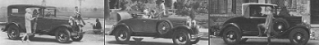
General Discussion / Compare 1929 Plymouth with Ford and Chevrolet? REVISED
October 04, 2009, 12:48:23 AM
Here is some interesting info taken from an article on the 1929 Plymouth that Special Interest Auto magazine did in 1997. Shows Plymouth's better features over the other two in its day. It is a jpg. file, just right click on it, go to the top tool bar, click "VIEW" and drop down to "ZOOM IN" (3-4 times) and it will zoom to read if needed. Lets try. Happy Motoring!!!! - Rich
#34
General Discussion / Steering Wheel Switch Wiring Sketch
September 28, 2009, 12:24:55 AM
You have to go to page #2 of the original thread for the wiring sketch. I missed seeing the #2 at the bottom at first.
#35
General Discussion / Anybody have experience with the coil ignition switch?
May 07, 2009, 10:32:45 PM Has anyone tried to take apart the ignition lock, switch and ignition coil on a 1929 Plymouth? I got as far as removing the nickle trim ring and two screws that hold another backing steel plate. The coil looks to be spot welded to the mounting bracket that has the three holes to mount the assembly to the dash. Could it be?? How would you change the coil? The lock assembly looks to be crimped in place to the top of the mounting bracket. There is a small hole (aprox. 1/8 dia.) in the bottom of the mounting bracket. Is it a drain or does it have a purpose for dis-assembly or ?? The idea was to try to change the coil to a N.O.S. one that I have and free-up the ignition switch at the same time. The pot metal lock assembly is a little tight. BUT maybe I won't. Any experience out there with this assembly? Happy Motoring!!!! - Rich
#36
General Discussion / My '29 Ply. 4 cyl. went to the machine shop this week
April 28, 2009, 10:34:32 PM
After finding a cracked piston and cylinders tapered about .010 the '29 Ply. 4 cyl. went to the machine shop this week. Waiting to see how it checks out. It didn't have much ridge at the top of the cylinders. Bores were smooth, exhaust valves need replacing, rod bearings look good, rings were free. Will update as it goes along.
#37
General Discussion / COMPARE '29 and '30 DETAILS
April 12, 2009, 10:52:23 PM
Internet info I thought interesting. (not sure if all info is correct but interesting)
Plymouth continues its rising sales, just about the only car to do so during the Great Depression. While styled nearly identically to the 1929 Model U Plymouth, the 1930 Model 30-U Plymouths had an "all steel" body. Externally the most visible change is to a wide radiator shell much more in keeping with the industry standard. The fuel gauge was moved from the top of the tank and put on the dash and becomes an electrical instrument. Hydraulic shock absorbers replace the earlier friction type. There were many running changes during production of the 30-U. Early production had a vacuum tank fuel pump. This changed to a mechanical fuel pump and a water pump was added. There were three different types of wire wheels used with three different bolt patterns. Early wood wheels were de-mountable rims while the later wood wheels were removable. On April 8th, 1930 production of the 30-U began with VIN number 1,500,001.
Happy Motoring!!!! - Rich
#38
General Discussion / FIBER DRIVE SHAFT DISCS
April 09, 2009, 10:01:51 PM Has anyone found a chart of the different sizes of fiber drive shaft discs as to physical size and bolt patterns from hole to hole for different model year cars? Please advise if available. Maybe member contributions to make a list of them could be posted for reference to the forum. Thanks - Rich SIZE CHART
FIBER DISCS for DRIVE SHAFT
FIBER DISCS for DRIVE SHAFT
- 1928-29 PLYMOUTH, 6 holes are 2 1/4 in. apart, 6 in. in dia., Center Hole 2 1/4 in. wide, 5/16 in. thick
- 27 Chrysler[/b] (
] [/list]
#39
General Discussion / 1929 Plymouth pistons
April 03, 2009, 11:23:49 AM I am looking for a suppler of pistons on a 1929 Plymouth 4 cylinder 3 5/8 in. Dia. See the request in the "HARD TO FIND PARTS" header of the forum. Thanks - Rich
#40
General Discussion / Steering Wheel Switch Wiring
March 18, 2009, 01:07:59 PM Can you supply the arrangement of the 6 wires to the switch on the end of the steering wheel on my 1929 Plymouth Coupe? The diagram in the manual shows it as a round switch and in reality they are in a straight line on the switch. Using the terminal closest to the engine as #1 and identify the correct wires that connect from there to the other 5 wires. Thank you for forum and the help. - Rich