The Floor Continued
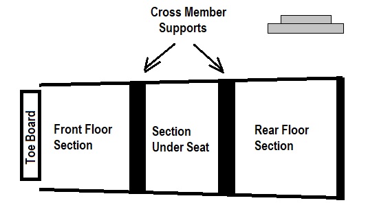
I will be working on the floor in 4 distinct sections. The diagram below shows my plan. All the floor sections will sit on a 3/4" railing installed onto the sill and designed into the cross members. I will be using two main cross members. The first positioned at the front of the front seat. The second positioned at the rear of the front seat. The floor attaching to both the toe board and rear seat will be support as required. This setup will allow the front floor and toe board to be removed while working on the transmission area. The rear section will allow for removal if one needs to get greater access to the rear axel and drive shaft.
My sill is one and three quarters of an inch in diameter so I cut rail sections from 3/4" thick hardwood to one inch in depth. This rail was installed the entire length of the required floor. Approximately 66 inches long. I am using 3/4" Maple plywood for the finished floor. The floor boards are trapezoidal with a 3 degree inward taper on both of the nonparallel sides.
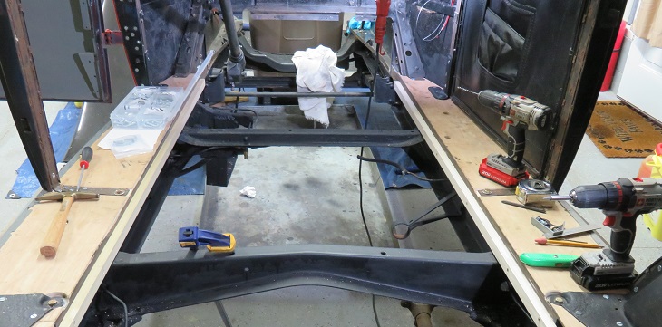
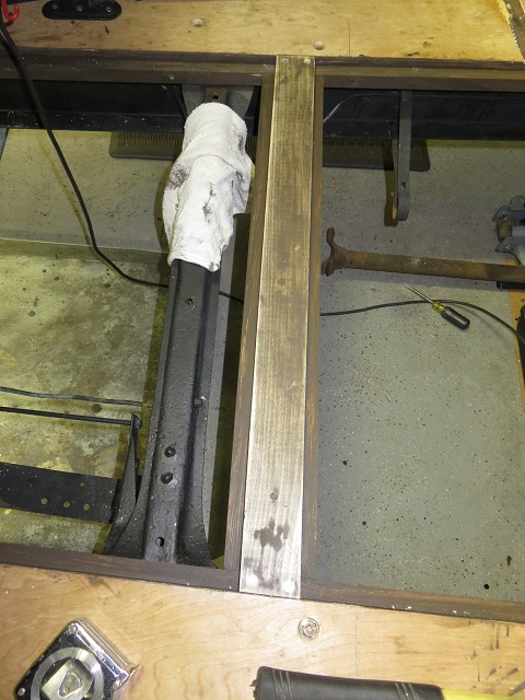
The cross members are made from two pieces of hardwood. The top section is 3/4" x 2.5 " wide. The bottom section is 3/4 x 4" wide. Combining these two sections creates the required 3/4" rail for the floor to rest on. The length of this member is cut to facilitate the position of the member in relation to the nonparallel sides. I positioned the front of the cross member approximately 22 inches from the back of the toe board which is 28" from the exterior firewall.
I had stained all the wood pieces and accidently stained the top of the front seat floor cross member. Not a problem because the floor will be painted and covered with rubber matting in the front and carpet in the rear. The picture below is the installed front seat cross member.
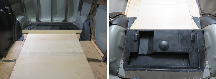
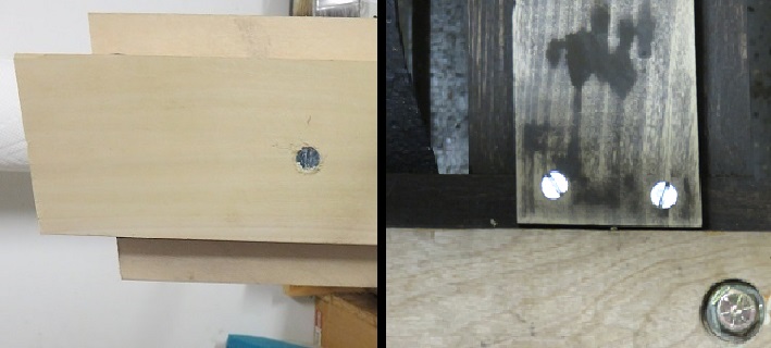
Cutting and fitting the floor boards is relatively simple in comparison to the frame structure. As I mentioned earlier there is a 3 degree taper along the non-parallel sides so getting an exact cut is possible by simply placing the uncut board into position and marking the cut edges from the underside of the car. Once I marked and cut the front floor section I needed to layout the opening for the battery box. I decided to allow the battery to be installed by dropping the battery through the floor. In order to accomplish this I created a 10" x 8 1/8" access hole. When you take into consideration the 3/4" floor rail and the 1/4 inch cover lip the actual hole size is 10" x 7 1/8" . This is just enough to be able to slip in a normal 6vdc standard battery. The dimensions I used are basically the size of the battery box frame. I mounted an 'L' shaped wood shelf which attaches to the floor rail at the top and is screwed into the metal frame at the bottom. See picture below:
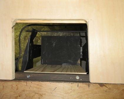
Below is a picture of the floor section installed. Notice that I rounded the battery box cover ends so that I could remove and use the cut section as the battery box cover. This cover section was cut with a jig saw.

The original floor had a smaller opening to access the battery. So in order to change the battery one would have to remove the front floor section. I cut a larger hole to access the battery without having to remove the front floor section.
With this accomplished I used the same procedure to create the next support cross member. I placed this member 18 inches from the back of the first cross member. This will allow for a floor section 18 inches in length under the front seat.
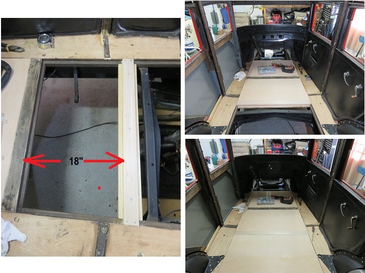
I measured and rough cut the rear floor section using the same steps as for the last two floor sections. I made this section slightly longer than I needed to so that I could trim it when I create the last cross member and rear seat pan support.
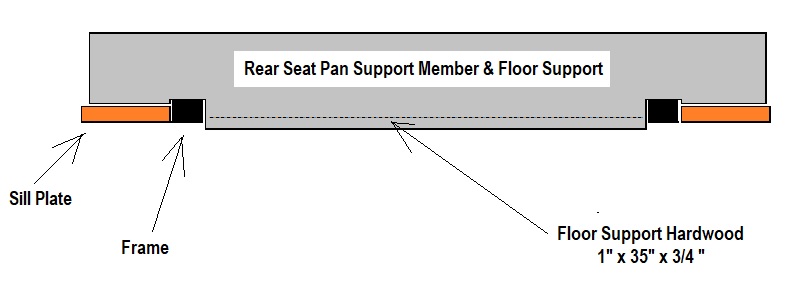
The rear seat pan support member I created from a leftover section of plywood and a piece of hardwood 1" x 3/4" which adds strength to the cross member and also provides an edge to support the rear section of the rear floor panel. This piece is different than the last two cross members in that it is perpendicular to the floor and sits on top of the sill and is cut to extend past the floor panel. See diagram below. This design is my own and I do not know how this was handled in the original Plymouth's construction.
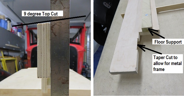
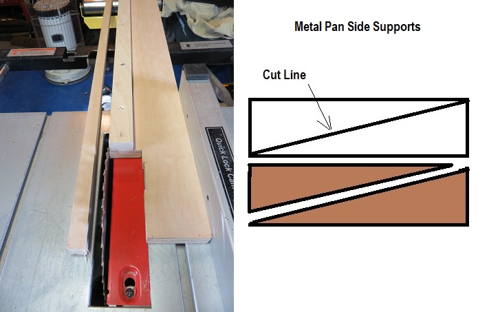
Once the glue was dry I trimmed the excess wood and painted the piece to provide weather protection. I measured and cut the side supports. I created these side supports by cutting a piece of plywood 3 1/8" wide by 16 3/4" long. I used the 3 1/8" width to compensate for the 1/8" saw blade. I cut this piece from long corner to long corner to produce the two side supports.
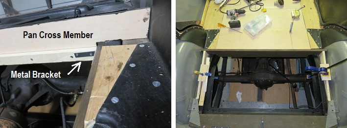
Once I had all the pieces created, installing the floor was pretty straight forward. I installed the pan cross member and glued the back seat pan sides to the main sills. I also install a metal angle support on both sides of the pan support member's floor ledge and the floor ledge of the main sills.
I think the finished product will work out great and should last another 100 years as long as the future owners take good care of this antique Plymouth U.