Reassembly - Electrical
In order to start the wire harness installation, there are a few mechanical items that need to be installed. This will be an ongoing necessity while installing the wiring harnesses. Since the harness may possibly run behind or in front of an item. To properly install the harness these items will also need to be permanently installed.
|
What I have installed prior to starting the electrical project.
|
 |
I am installing a YnZ wire harness. The harness has been modified and fitted with a removable harness for a steering wheel signal flasher. Wires were added to the harness for front and rear 4-way flasher lights. The added rear lights will also be removable without any modification to the single rear light functionality. This means for a car show these items may be removed for the show and reinstalled for the drive home. This was a modification that I had previously installed in this car but now it will be permanently added and properly hidden within the wire loom.
|
The harness is in three main sections.
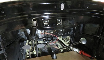
What better place to start than the dash out to the engine compartment. As you can see in the picture to the right, the harness splits into two sections. The smaller single wire split to the left is the main power feed from the battery side of the starter switch. The larger section to the right are the wires for the lights and will connect up with the front and rear harnesses. |
 |
I will be installing an inline fuse connection between the dc generator and the amp gauge. I will also install another inline fuse for the ignition and accessory circuits. If you review this on your wiring diagram you will see that the battery and the generator are connected together from both sides of the amp gauge. If the generator or its wiring shorted this circuit is not fused and will draw maximum current which would create damage to the associated wiring. This has happened to me in the past and the result is a generator wire glowing like an electric stove burner. This is not good so a 15 amp fuse will protect against this type of failure and be hidden from view. In the stock wiring diagram the only circuit the barrel fuse protects is the line going to the horn and then to the lighting switch.
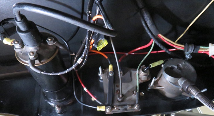
Explanation of the picture above:
|
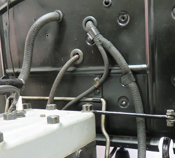
| Moving on to the engine
compartment I needed to install the Horn which is necessary to
complete the power connection to the light switch. I then proceed to snake the rear harness section down the inside driver's side frame. Remember my harness is a lot bigger than the stock harness because it contains additional wiring for the flasher system. This work was very easy to accomplish. The harness shares mounting clips with the brake lines. The harness runs from the light switch down the frame behind the battery box. This harness also includes the wires which attach to the brake light switch. The picture to the right shows the dash harness meeting up with the harness for the rear lights. |
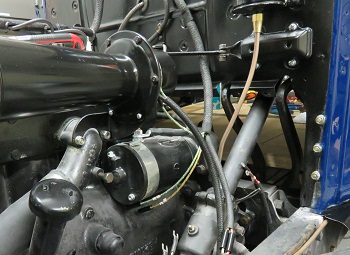 |
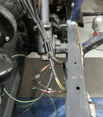
| Installing the front
harness was quick and easy. Keep in mind that I am not
connecting the lights just getting the harnesses in place to
facilitate the installation of fenders, bumpers, and of course the
light fixtures. All components under the dash are completed as well as the wires going to the horn and the master cylinder brake light switch. The picture to the right shows where these three harnesses come together. I connected the three harnesses together and dressed the wiring so that it looked as neat as possible. There are 5 harness point connections leaving an additional 5 connection points remaining to be attached to the steering column switch. All in all this seemed overwhelming but in retrospect uneventful. The next step in this electrical project will be replacing the horn button wire and reinstalling the steering column switch. |
 |