Reassembly Electrical - CLUM Switch/Horn Button
Before I can install the Column Switch I needed to replace the horn wire. Not doing this would be just plain wrong. I am a firm believer in the old adage "if it ain't broke don't fix it" but in this case after 90 years, failure is imminent and since the roof is open this extremely hard task is now relatively easy. Everything in this area is extremely hard to replace if broken, so great care has to be taken. The switch arms and the column switch are next to impossible to find in useable condition.
|
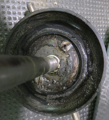
Once the column switch assembly is removed there are two screws on the underside of the assembly which holds everything together.
First step is to remove these screws. The picture below and to the left is a quick diagram showing the internal parts of the horn button assembly which caps the steering column. |
 |
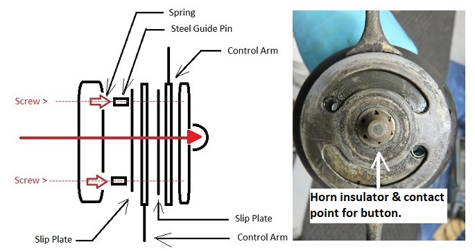
Explanation of the diagram above starting from left to right:
|
I removed all the sections and cleaned the individual parts so they will operate properly once assembled. Cleaning also helps provide good electrical continuity.
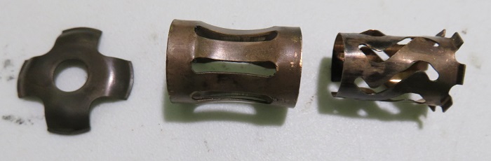
Note on the grounding of the steering column: The picture below shows the copper items providing a good ground to these moving parts.
-
The item to the left is a tensioning support that goes between the CLUM switch and the throttle shaft.
-
The middle item is a copper ground which I accidently removed from the steering wheel shaft when I ran a patch through it. If you should do this by accident like I did. It can be inserted back into the tube from the bottom of the steering column shaft using a half inch wood dowel. As you push it up into the steering tube you will feel it fall into its detent. Do not try to insert this part from the steering wheel side of the tube. The hole is two small.
-
The last item to the right is another grounding contact and this inserts into the top of the steering wheel shaft. Ensure this is installed prior to reinserting the switch tube assembly.
I replaced the old horn wire with a 14 gauge stranded wire and also replaced the contact button in the insulator. The picture below shows how these items come together.
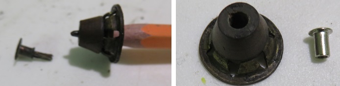
In order to make a good solid connection to the new horn button contact, I tinned the wire with solder, then inserted it into the new contact. I lightly compressed the contact shaft to affix it to the tinned 14 gauge wire. This makes it easier to solder. I supported the wire in my bench vice and soldered it to the new tip. Once the solder started to run the tinned wire inside the tip made for an excellent soldered connection point.
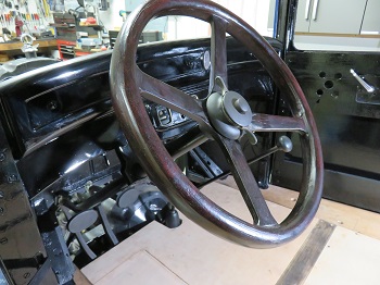
Once this was finished I reassembled the switch tube assembly and inserted it back into the steering wheel tube.
|
Now you would think that the hard part was over with. Think
again.
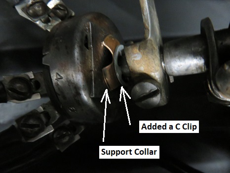
Trying to keep pressure against the switch assembly and tighten the collar screw, kept moving the switch arm into the wrong position. |
 |
| When I finally got the
switch aligned properly, there was no tension on the support collar.
I tried over and over again but I think there was too much play in the switch assembly itself to make tight contact with the support collar. I resolved this problem by inserting a 'C' clip between the support collar and the throttle shaft. This little trick snugged up everything nicely. I checked out the positioning of the switch arms to ensure proper alignment. I also used a continuity tester to ensure proper electrical functionality. Finally after many tries things were as they should be. |
 |
| Now that everything was
together and working properly I spent some time wiring up the switch
and dressing the wires. For informational purposes, looking down at the switch pictured on the right; the posts are numbered from left to right as follows: 1 - 3 - 2 - 4 - 6 - 5 Please note: that the #2 position on my switch is missing but this is only a lug for connecting the horn wire to the horn assembly. There is no switch functionality for this position. (Dummy Point) Wire 1 - Power and feed to Master Cylinder. (Power) Wire 3 - Park Lights Wire 2 - Horn Button to Horn Wire 4 - High Beam - Headlamp Wire 6 - Low Beam - Headlamp Wire 5 - Feed to Tail Light |
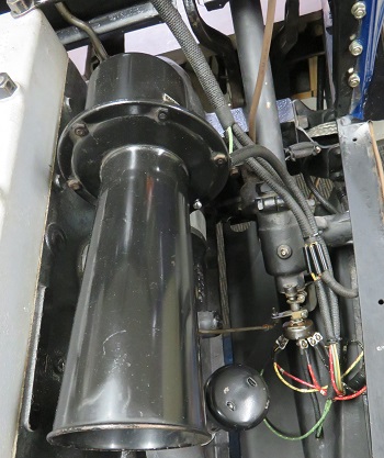 |
I finished up this part of the project by installing the gravel pan below the steering assembly. Yes you are correct the horn pictured above is not the stock Plymouth horn assembly. It is a vintage EA circa 1925 r-Ooooga horn very cool.